: Managing Supply Pressure Effect (SPE) in a Regulator
Managing Supply Pressure Effect (SPE) in a Regulator
Fluid system operators running a process line from a gas cylinder source may occasionally observe the phenomenon of outlet pressure increasing in a pressure-reducing regulator for no apparent reason. As the cylinder empties, the inlet pressure to the regulator decreases. Many skilled technicians would expect the outlet pressure to decrease concurrently, but instead, the outlet pressure rises. This occurrence is known as supply pressure effect (SPE).
What is Supply Pressure Effect (SPE)?
Supply pressure effect, also referred to as inlet dependency, is defined as the change in outlet pressure due to a change in inlet, or supply, pressure. Under this phenomenon, inlet and outlet pressure changes are inversely proportional to each other. If the inlet pressure decreases, there will be a corresponding outlet pressure increase. Conversely, if the inlet pressure increases, the outlet pressure decreases.
A regulator’s supply pressure effect is typically provided by the manufacturer. SPE is usually depicted as a ratio or percentage describing the change in outlet pressure per change in inlet pressure. For example, if a regulator is described as having a 1:100 or 1% SPE, for every 100 psi drop in inlet pressure, the outlet pressure will increase by 1 psi. The degree of outlet pressure variation for a regulator can be estimated with the following formula:
∆P (outlet) = ∆P (inlet) x SPE
Unbalanced vs. Balanced Poppet Design in Spring-Loaded Regulators
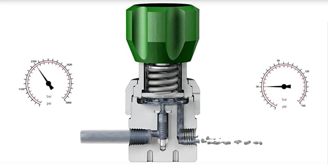
One of the most common types of regulators is a spring-loaded pressure-reducing regulator. A spring applies force on a sensing element, either a diaphragm or a piston, which controls the poppet over the orifice—therefore controlling the outlet pressure.
In an unbalanced poppet design, the inlet pressure pushes up on the poppet and applies pressure to a portion of the poppet equal to the seat area. As a result, any decrease in inlet pressure means less force is pushing up on to the poppet, allowing the strong set spring to push the poppet slightly further from the seat—thus increasing the outlet pressure. This resulting rise in outlet pressure is not strong enough to fully counterbalance the set spring force to close the poppet to its original position. The outcome is an increase in outlet pressure due to supply pressure effect.
Because regulators operate on a balance of forces, the amount of SPE can be determined by the ratio of areas on which pressures acts on the poppet and sensing areas. That is to say that regulators with large sensing areas and small poppets will have the lowest SPE and those with small sensing areas and large poppets will have the highest SPE.
To demonstrate the effect of an unbalanced poppet design on supply pressure effect, gradually decrease the inlet pressure. At an inlet pressure of 1160 psig (80 bar), the outlet pressure is 43.5 psig (3 bar). But when inlet pressure is decreased to 870 psig (60 bar), the outlet pressure jumps to 53.7 psig (3.7 bar). Since the inlet pressure acts on the entire surface of an unbalanced poppet, any change in inlet pressure produces a large change in force, driving a bigger shift in the balance of forces within the regulator.
A common method for reducing supply pressure effect, especially within higher-flow applications where poppets are generally larger, is to use a regulator with a balanced poppet design. The intention of this regulator design is to minimize the area on which the high inlet pressure can act. This is accomplished by allowing the lower outlet pressure to reach a portion of the underside of the poppet through an orifice that runs vertically along the poppet and sealed by an o-ring around the lower stem of the poppet. In terms of supply pressure effect, any change in inlet pressure will result in a smaller change in force because the pressure is acting on a much smaller area.
To demonstrate how supply pressure effect impacts a balanced poppet regulator, envision gradually decreasing the inlet pressure as demonstrated previously with the unbalanced poppet design. Just as before, at an inlet pressure of 1160 psig (80 bar), the outlet pressure is 43.5 psig (3 bar). However, when inlet pressure is decreased to 870 psig (60 bar), the outlet pressure only increases to 46.4 psig (3.2 bar). In fact, even at an inlet pressure of 725 psig (50 bar), the outlet pressure continues to hold steady at 46.4 psig (3.2 bar).
Notice how the effect on the outlet pressure with a balanced poppet regulator is lessened from the previous regulator arrangement. An added benefit of a balanced poppet regulator is the ability to reduce lockup—avoiding potential spikes in outlet pressure when the poppet closes rapidly.
Single-Stage vs. Two-Stage Regulation
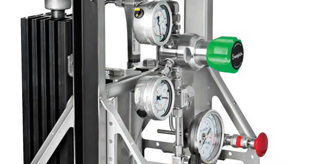
For lower-flow applications, like analytical instrumentation systems, an alternative method of minimizing supply pressure effect is to use two-stage pressure reduction. This method involves installing two single-stage regulators in a series or combining the regulators into one assembly. Each regulator controls the inlet pressure variation to a certain degree but together, the two regulators keep the outlet pressure very close to the original set point.
To calculate the variability of outlet pressure for a two-stage regulator setup, the inlet pressure difference is multiplied by the SPE of each regulator. This is illustrated in the following equation
∆P (outlet) = ∆P (inlet) x SPE1 x SPE2
Keep in mind that SPE is an inverse relationship between inlet and outlet pressure variables. The first-stage regulator will encounter an increase in outlet pressure as the gas cylinder empties and inlet pressure decreases. This increase will be fed into the second-stage and result in a succeeding decrease on the outlet side of the second-stage regulator. Because the first-stage regulator experiences the large inlet change and outputs a smaller outlet change, the second-stage regulator reacts only to the small inlet change from the first-stage and shows minimal pressure decrease on the outlet side.
To demonstrate supply pressure effect, the below example uses a KCY model pressure-reducing regulator. The gas cylinder empties from 2500 psig (172 bar) to 500 psig (34 bar). Assume that each regulator has a 1% SPE. With a 2000 psig (137 bar) inlet pressure drop, the first-stage regulator will experience a 20 psig (1.3 bar) increase in outlet pressure. As a result of that increase, the second-stage regulator will only experience a 0.20 psig (0.01 bar) decrease in outlet pressure. Notice how the effect on the outlet pressure is dramatically lessened from the previous regulator arrangements.
In terms of controlling supply pressure effect, a two-stage regulator setup typically will achieve a better outcome than a single pressure-reducing regulator with a balanced poppet. In an application using one gas cylinder to source multiple operations under the same outlet pressure, either option may be sufficient.
On the other hand, applications that require a gas cylinder to supply multiple operations with different pressures will need to use two single-stage regulators to make a two-stage regulator system. If this is the case, set-up the first-stage regulator near the gas cylinder and the second-stage regulator on each of the process lines. Commonly, in an effort to minimize SPE, systems are built with a two-stage regulator at the gas supply source and a single-stage regulator at the point of use. This excessive setup amounts to three-stage regulation—which is unnecessary for the large majority of applications. Two single-stage regulators in series will yield minimal SPE at a lower cost.
Conclusion
With the regulator controlling outlet pressure from a gas cylinder, supply pressure effect is a phenomenon that will always be present. Whenever there is a change in inlet pressure, there will be a corresponding change in outlet pressure. You can minimize supply pressure effect for many applications by using a single-stage regulator with a balanced poppet design or by using a two-stage regulator. But if your gas source is servicing multiple operations with different pressure requirements, you may need multiple single-stage regulators—one near the gas source and another on each process line.
Need help selecting the right regulator for your fluid system application? Swagelok can help you identify solutions to improve operations based on your unique systems. To learn more, take a look at our library of Tech Tip Videos about managing a regulator’s supply and flattening regulator curves.
Related Highlights
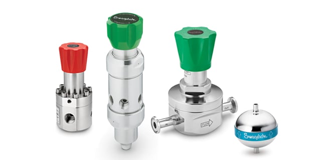
Pressure Reducing & Spring Loaded Regulators
Reliable pressure control is essential to the safe operation of your fluid systems.
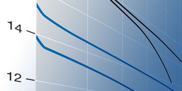
Regulator Flow Curve Generators
The tool that give you a unique flow curve based on a set of user-specified application parameters for RHPS series regulators.
Analytical Subsystems
Analytical subsystem are designed by engineering expert and field-tested design to ensures optimum system performance.